top of page

ASSIGNMENT 4B: 2.5 AXIS MOTION SYSTEM

The goal of the assignment is to apply the concepts and methods that were previously reviewed in class for the design and assembly of a 2.5 Axis Motion System.

The Learning Objectives are:

  • To devise different ways to embody ideal joints such as revolute, prismatic, spherical and/or universal joints.

  • To design mechanical components with rational shapes, considering their function, mechanical loading, required accuracy, method of fabrication and assembly.

  • To integrate and test a product prototype with mechanical and electrical components.

The design challenge is to build a system that is small and lightweight enough so that it can be easily carried in a backpack. The design of the device can be totally or partially disassembled for transport, as long as it can be assembled by one person in no more than 10 minutes.

The device will comprise the structure and motion elements (stepper and servo motors, pulleys, linear guides and belts).

​

*Please click on pictures (below) to enlarge and show more details*

*TO SEE ARDUINO CODE, PLEASE CLICK ON THE PICTURE AND THEN CLICK ON LINK TO OPEN PDF*
ME360 Asgmt 4: 2.5 Degrees of Freedom: About
ME360 Asgmt 4: 2.5 Degrees of Freedom: Work

Project Debrief:

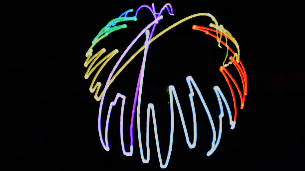
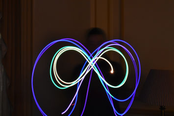
This project primarily operates on the principles of Long Exposure Photography where a stable camera is set up to take in light over a very long period of time and combines the images taken into 1 picture. The task of this project is to design a 2.5 Degree of Freedom system with which a certain action can be completed. The 2 degrees of freedom of this project is in the theta and phi directions (if using spherical coordinate system). The half degree of Freedom was achieved through the usage of a multi colored Neopixel LED Bulb which would either be a certain color or off. This project was designed so that it could be easily disassembled by removing the LED "Brush" Arm and unplugging the Data In wires from the Arduino. The controller joystick is also easily disconnected from the assembly by unplugging the attached ribbon cable. The main housing was designed to be compact, lightweight, and functional.

​

To actuate the movements, a stepper motor was used for the theta direction due to it having a high degree of control in 360 degrees and a servo motor was used for the phi direction due to it having control across 180 degrees (since the table or supporting structure would prevent the arm to move past this physical constraint).

​

The primary gearing structure was 3D printed to operate with the given drive belt and gears. The protective dome encasing the project was done using a thermoforming. Finally, the name and bottom plate of the project was fabricated using Laser Cutting and Engraving.

​

The electronics and coding of this project were the more challenging areas of this project. A significant obstacle during fabrication was the restriction that the wires of the LED and Servo Motor gave. Since the entire device rotates about the Z axis, the wires would experience both tension and torsion after a few rotations causing them to unplug themselves from the Arduino. A few solutions were designed to prevent this but there was not enough time to test and implement them. Firstly, conductive paint was considered as a viable alternative to wires where the signal and power would be delivered through a brushed system (Similar to how brushed motors work). Another possible solution was to use strips of conductive material around the inside of the dome and a metal contact that would connect and power the required components. While the final product did not feature these solutions, it was still able to safely perform a maximum of 3 to 4 rotations before a hard stop prevented any further rotations.


Currently for controls, a 2 axis joystick with a button was used. The Y axis would control the Servo Motor, the X axis would control the Stepper Motor, and the button would operate the LED. The code implements a case system (Please download the ControlCode PDF for changelog) to control everything. It was also originally planned to be able to input a matrix of coordinates so that the apparatus could run autonomously however that requires a lot more calibrations than the time allotted for this project.

​

If a second iteration of Das Brush^3D were to be made, it would be made with the aforementioned hardware improvements as well as a wireless controller so that the artist would not be constrained to an area around the apparatus. Other improvements could also be made with the use of multiple Arduinos as that would allow the bulb and motors to operate independently of each other resulting in a more flexible product.

ME360 Asgmt 4: 2.5 Degrees of Freedom: Quote
ME360 Asgmt 4: 2.5 Degrees of Freedom: Work
ME360 Asgmt 4: 2.5 Degrees of Freedom: Quote

©2020 by Shane Xu. Proudly created with Wix.com Last Updated August 2021

bottom of page